Recently, we had a customer bring their 2014 Mazda 3, 2.0L to us to install an oil catch can kit and to perform its very first oil change. With the car being so new, we asked if it would be OK to have a look inside at the current condition of the valves and document our findings. The car wasn’t to be picked up until the following day so we were given the go ahead. With only 4462 miles on it, wait until you see what we found!

OK, so what is the PCV system and why is there a need for one? PCV stands for Positive Crankcase Ventilation. Simply put, the purpose of the PCV system is to ventilate the lower half of the motor that contains the motor’s crankshaft, connecting rods and balance shaft. When the motor is running under normal operating conditions, the oil becomes very hot. As the motors rotating assembly spins at very high RPM, a considerable amount of pressure is built up that must be relieved. For obvious reasons that we’ll go into more later, this can’t just be vented to the atmosphere. Instead, the hot vapor is released from the crankcase, routed into the intake manifold and burned as part of the combustion process. Sounds like a logical and efficient approach to the problem. Unfortunately, the vapor released from the crankcase contains trace amounts of oil, fuel and water. Let’s take a closer look at what makes up the PCV system and the path it takes back to the combustion chamber.
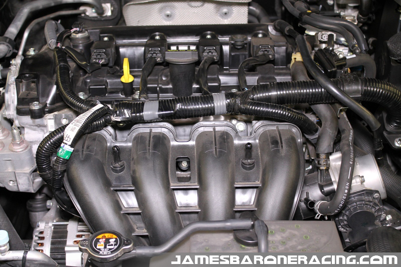
Let’s begin with the removal of the intake manifold. It’s pretty easy and took less than 25 minutes to get out of the car.
Immediately, things began to start looking ugly. With the manifold removed we found the presence of oil on the head, in the gaps created by seals between the cylinder head and the intake manifold. Click on any of the pictures for a larger view.
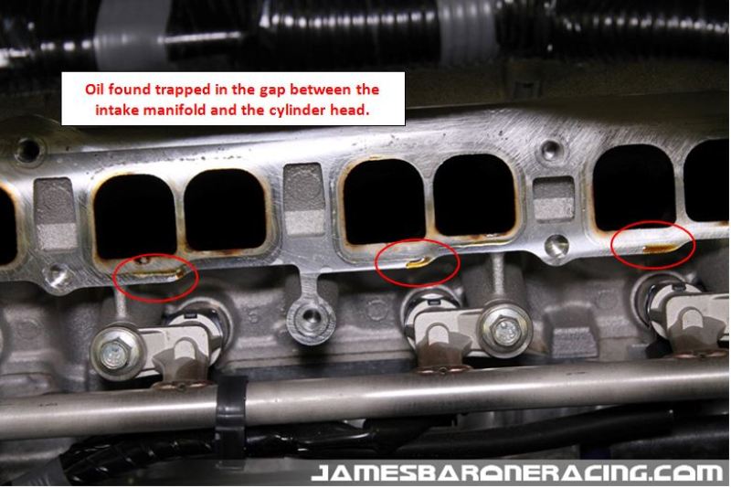
The next picture illustrates where the intake manifold mates with the cylinder head ports from the passenger side, port 1, towards the driver’s side, port 4. The seals that create the gap between the two are green and surround each intake runner. Take note of the proximity of the ports in relation to where the line leading from the PCV valve enters the intake manifold.
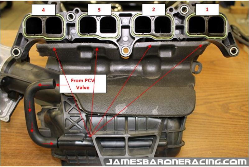
The next series of pictures will show the astonishing amount of carbon accumulation we discovered on the valves beginning with cylinder 1, the furthest from where the crankcase vapor enters the manifold.
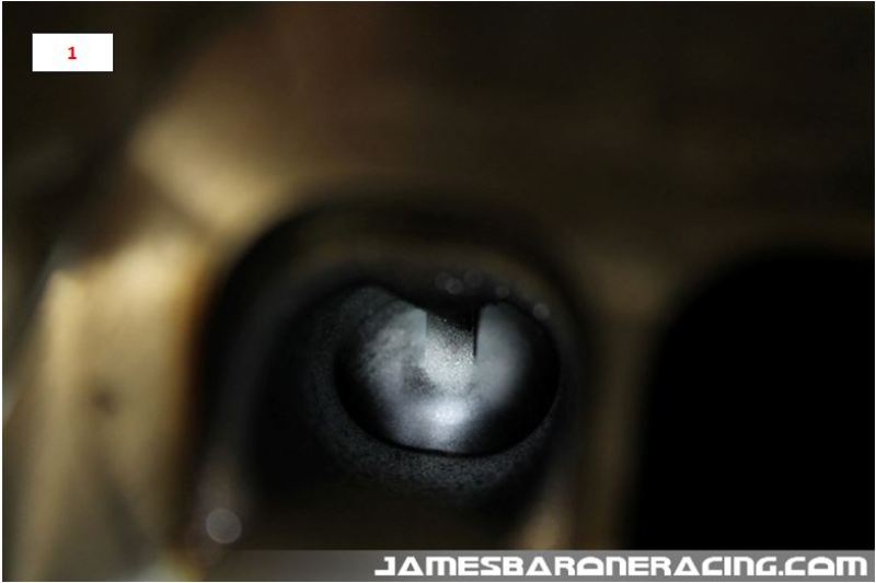


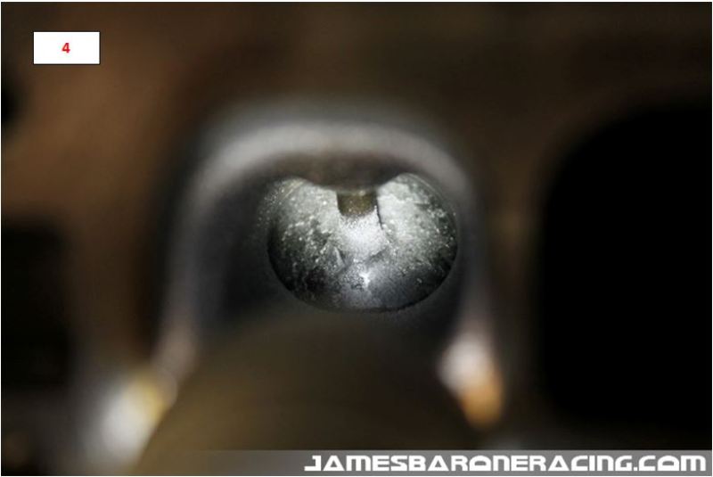
As you can see from the pictures above, the valves for cylinder 1 are pretty clean and what we expected to see. As we moved to cylinders 2 thru 4 though, we can see significant accumulation, the worst being cylinder 4. The oil in the vapor is adhering to the back side of the hot valves and subsequently, it’s being baked on forming an impressive crust for such low mileage. The assumption for the increased build up from 1 to 4 is due to their proximity to where the crankcase vapor enters the intake manifold.
Why is this build up of crust bad? The valves are designed to seat in machined surfaces within the cylinder head. This creates the needed compression when it’s time for that particular cylinder to fire. When the build up of carbon becomes excessive, the valves are no longer able to seat properly, reducing power that robs your engine of performance and increases the amount of money you spend at the pump.
We reinstalled the intake manifold, changed the oil and installed our oil catch can kit. When the customer came to pick up the car we explained what we found, reviewed the pictures and agreed, this motor will certainly benefit from an oil catch can.
So that brings up the next question, what is an oil catch can and how does it work? An oil catch can is a can that contains some form of baffling that captures the oil present in the vapor released from the crankcase. The can is plumbed in-line between the crankcase and the intake manifold. Let’s take a deeper look into the catch can and the PCV system.
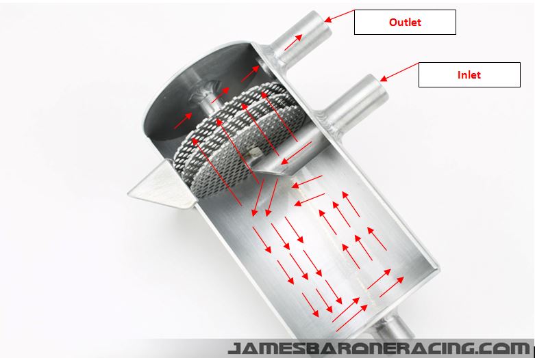
In this cut-away of the JBR oil catch can, you will see the inlet, the outlet and the baffling that separates them. The crankcase gas enters the catch can through the bottom port. Due to the size of the can, a pressure drop occurs as the gas enters allowing for oil to begin falling out of suspension. As the gas travels around and eventually up towards the outlet, it must pass through a series of three perforated baffles with hundreds of .063″ holes in each. Not only do the holes in the baffle plates greatly increase the amount surface area, a capillary action is also created. That, combined with surface tension, results in adhesive forces between the oil and holes in the baffles. The oil clings to the baffles and as it accumulates it drips off and is collected in the bottom of the can to be drained off at each oil change.
Well if this is such a problem why isn’t Mazda including one? Well, they are, sort of. It’s called an oil separator and it’s located on the side of the engine block behind the intake manifold.
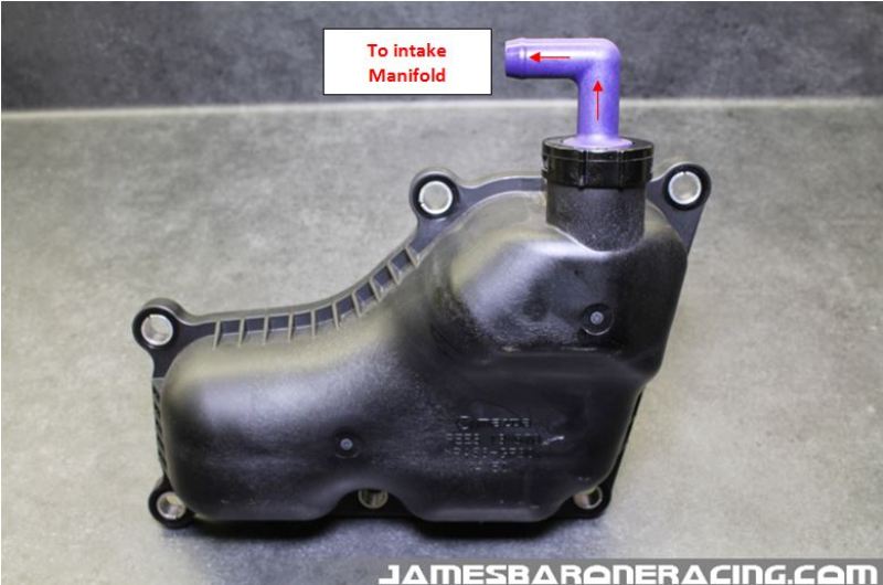
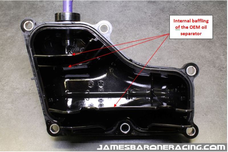
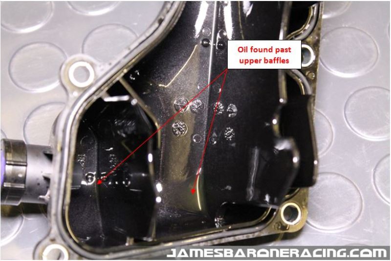
When we removed the oil separator from our 2016 Miata with the same 2.0L motor as our customer had, we found oil making its way past the baffling headed towards the outlet of the oil separator. It appears to work, just not very well.
At the time we tore into our new Miata it only had 31 miles on it so everything was nice and clean. After seeing what we saw on the same motor with only 4463 miles, a catch can was going on immediately!
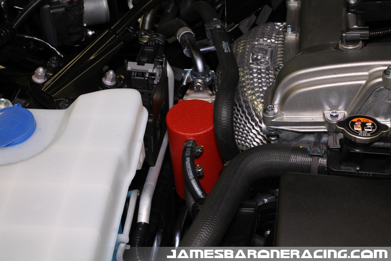
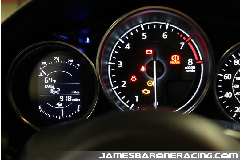
With just over 900 miles it’s time for us to change the oil in our Miata.
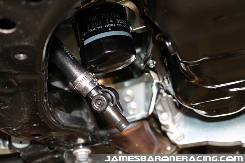
With the drain for the catch can located right by the filter housing, we can easily open the valve and empty its contents.
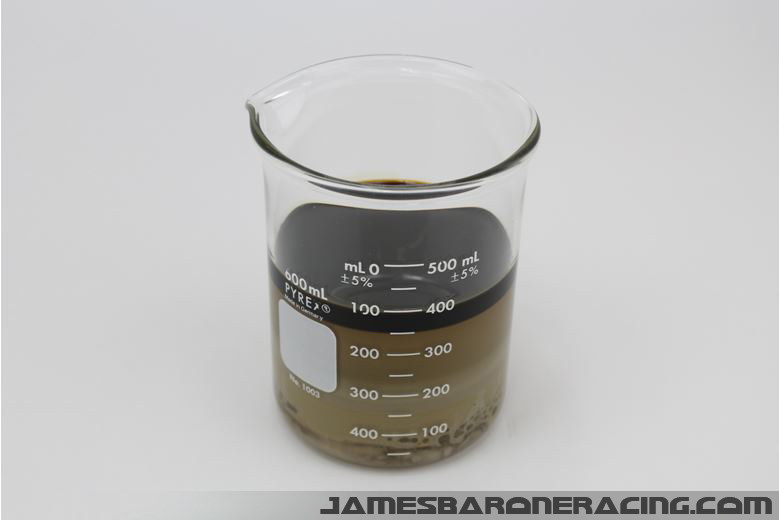
We were pleased to discover that we had accumulated a mixture of oil, water and fuel just shy of 50ml! Our catch can is doing its job well and our valves are being kept as clean as possible.

Below is a picture of the typical amount collected from our Mazdaspeed 3 at its regular 5k mile service interval. After it’s allowed to sit for a few days, there’s pretty clear separation of the oil, water and fuel that’s collected.
We’ve been making and testing Oil Catch Can Kits for most Mazda’s and a few Ford vehicles for several years now. It’s our opinion that any engine utilizing direct injection fueling can only benefit from an oil catch can.
On a separate note…Many customers have asked if warranty claims can be denied for having a catch can installed? The answer is yes however, it’s highly unlikely and the burden of proof falls on the dealership to prove the catch can was the direct cause and ultimately the reason for the warranty claim in the first place. We’ve never heard of a warranty be denied for a vehicle having a catch can installed.
We’ll be sure to provide future updates on both our customer’s Mazda 3 and our Miata in the upcoming year to see how both are doing.


